- info@moretec-inc.com
- |
- CN
- |
- JP
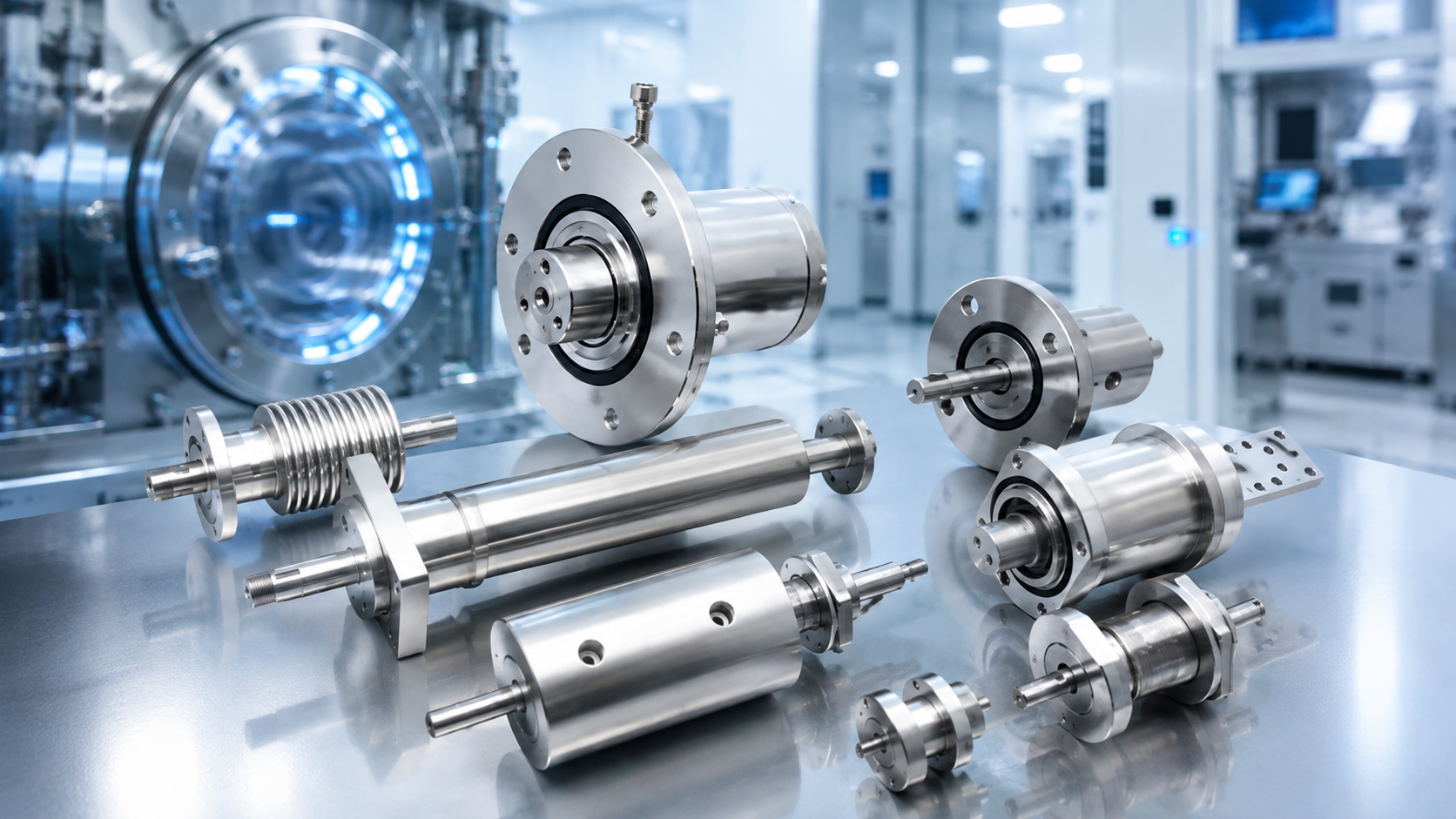
Semiconductor manufacturing requires reliable components to maintain vacuum stability, contamination control, and precise mechanical movement. In many semiconductor systems, rotary motion must be transmitted through a vacuum chamber without compromising process conditions.
A ferrofluid feedthrough uses magnetically retained ferrofluid to form a stable sealing barrier around a rotating shaft. Compared with conventional contact-type seals, the sealing interface minimizes solid-to-solid contact, helping reduce wear and particle generation while maintaining reliable vacuum isolation.
Moretec provides standard and customized ferrofluid feedthrough solutions for semiconductor, vacuum coating, and other advanced industrial applications.
Semiconductor processes often require mechanical rotation inside high-vacuum environments. Typical applications include:
CVD
PVD
Etching
ALD
Ion implantation
Vacuum coating
Wafer processing
Precision vacuum equipment
In these systems, the feedthrough must transmit rotary motion while maintaining vacuum integrity.
Traditional contact-type seals may experience friction and wear during continuous operation. This can increase maintenance requirements and generate particles at the sealing interface.
A ferrofluid feedthrough uses magnetic force to retain ferrofluid between the shaft and magnetic pole pieces. The ferrofluid forms multiple liquid sealing stages, creating a reliable barrier between the vacuum side and atmosphere.
Key benefits include:
Stable vacuum sealing
Low particle generation at the sealing interface
Reduced sealing wear
Smooth rotary transmission
Long operating life when properly selected
A typical ferrofluid feedthrough consists of:
Rotating shaft
Permanent magnet
Magnetic pole pieces
Ferrofluid
Bearings
Housing
The magnetic circuit concentrates magnetic flux in the small gaps between the shaft and pole pieces. Ferrofluid is attracted to these regions and forms a series of sealing rings.
Each sealing stage can withstand a certain pressure difference. Multiple stages are therefore used to maintain the required differential pressure between atmosphere and vacuum.
Because the primary sealing interface is liquid rather than a conventional solid rubbing seal, sealing-interface wear is significantly reduced.
However, the feedthrough still contains mechanical components such as bearings. Overall performance and service life therefore depend on operating speed, load, temperature, cooling, and installation conditions.
Selecting a ferrofluid feedthrough requires evaluating the complete operating environment rather than simply matching dimensions.
| Selection Factor | Why It Matters |
|---|---|
| Vacuum level | Determines required sealing performance |
| Pressure differential | Influences sealing-stage design |
| Rotation speed | Affects heat, torque, and service life |
| Radial and axial load | Influences shaft and bearing design |
| Shaft configuration | Determines mechanical integration |
| Operating temperature | Affects ferrofluid and bearing performance |
| Process gas | Requires material and ferrofluid compatibility |
| Duty cycle | Influences thermal design and lifetime |
| Mounting interface | Determines equipment compatibility |
| Cooling requirement | May be required for demanding applications |
These factors should always be considered together.
For example, a low-speed feedthrough carrying a large radial load may require a different bearing arrangement from a high-speed unit with minimal external load.
Vacuum level is one of the most important selection parameters.
Semiconductor equipment may operate under high-vacuum or ultra-high-vacuum conditions depending on the process.
Engineers should evaluate:
Required vacuum level
Maximum allowable leak rate
Maximum pressure differential
Process gas
Atmospheric or positive pressure on the opposite side
Vacuum level and pressure differential are different parameters.
Even if the vacuum side operates at very low absolute pressure, the feedthrough may still need to withstand approximately one atmosphere of differential pressure.
The magnetic circuit and number of ferrofluid sealing stages must therefore be designed according to actual operating conditions.
Rotation speed directly affects feedthrough performance.
Heat can be generated by:
Ferrofluid viscous drag
Bearing friction
External mechanical loads
Shaft dynamics
Higher temperature can affect ferrofluid properties, bearing life, and overall reliability.
For demanding applications, water cooling may be required.
Important operating data includes:
Maximum speed
Normal operating speed
Continuous or intermittent operation
Ambient temperature
Vacuum-side temperature
External heat sources
Cooling conditions
The theoretical maximum speed of a feedthrough should not automatically be considered suitable for continuous operation under every load condition.
Mechanical loads are also critical to feedthrough selection.
External equipment may apply:
Radial load
Axial load
Belt tension
Gear load
Coupling load
Moment load
These loads are transferred to the feedthrough shaft and bearings.
Excessive load may significantly reduce bearing life even if the ferrofluid sealing section itself remains functional.
For customized designs, Moretec recommends providing:
Radial load
Axial load
Load direction
Load application point
Distance from the mounting face
Shaft-side mechanical layout
This information helps determine the correct shaft and bearing arrangement.
Different equipment designs require different shaft structures.
A solid shaft ferrofluid feedthrough is commonly used when the main requirement is mechanical rotary transmission.
Typical applications include:
Wafer rotation
Substrate rotation
Vacuum coating systems
Rotary fixtures
Precision positioning mechanisms
A hollow shaft ferrofluid feedthrough provides a central through-bore.
Depending on the equipment design, the bore may accommodate:
Customer shafts
Tubes
Cables
Sensors
Electrical connections
Other internal components
Hollow shaft designs are useful when both rotary transmission and a central passage are required.
The inner diameter, outer diameter, speed, load, and sealing structure should be selected according to the actual application.
Moretec can support different ferrofluid feedthrough configurations, including:
Flange-mounted designs
Thread-mounted designs
Nut-mounted designs
Solid shaft designs
Hollow shaft designs
Water-cooled designs
Bearing-integrated designs
Customized cartridge-style designs
Customer-specific mounting interfaces
For new equipment projects, providing installation drawings or mating dimensions can significantly improve design accuracy.
Process gas should also be evaluated during feedthrough selection.
Semiconductor equipment may use gases such as:
Nitrogen
Argon
Oxygen
Hydrogen-containing mixtures
Inert gases
Process-specific gases
Gas composition can influence the selection of:
Ferrofluid
O-rings
Shaft materials
Housing materials
Surface treatment
Lubricants
Customers should therefore provide gas composition and concentration whenever possible.
Some applications can use standard feedthroughs, while others require customized designs.
Customization may be necessary for:
Special shaft diameters
Special hollow-bore dimensions
Customer-specific flanges
Limited installation space
High radial or axial loads
Special process gases
Water cooling
High-temperature applications
Special materials
Special bearing arrangements
Moretec supports both standard and customized ferrofluid feedthrough solutions based on actual operating conditions.
To recommend a suitable ferrofluid feedthrough, customers should provide as much of the following information as possible:
Vacuum level
Maximum pressure differential
Normal and maximum rotation speed
Continuous or intermittent duty
Radial load
Axial load
Operating temperature
Process gas
Shaft dimensions
Solid or hollow shaft requirement
Mounting interface
Installation space
Cooling conditions
Equipment layout
This information helps determine the magnetic sealing structure, shaft design, bearing arrangement, and thermal requirements.
Moretec provides ferrofluid sealing solutions for applications including:
Semiconductor manufacturing
CVD
PVD
Etching
ALD
Ion implantation
Vacuum coating
Precision positioning systems
Scientific and industrial vacuum equipment
Moretec supports standard and customized solid-shaft, hollow-shaft, flange-mounted, threaded, and water-cooled configurations.
By evaluating both vacuum and mechanical operating conditions, Moretec helps customers select or develop suitable rotary vacuum sealing solutions.
Selecting the correct ferrofluid feedthrough for semiconductor equipment requires careful evaluation of:
Vacuum level
Pressure differential
Rotation speed
Radial and axial loads
Shaft configuration
Temperature
Process gas
Duty cycle
Cooling
Mounting interface
Ferrofluid sealing technology offers stable vacuum isolation, low particle generation at the sealing interface, reduced sealing wear, and reliable rotary transmission.
Moretec provides standard and customized ferrofluid feedthrough solutions for semiconductor and advanced vacuum equipment.
A ferrofluid feedthrough is a rotary vacuum sealing component that uses magnetically retained ferrofluid to transmit rotary motion through a vacuum chamber wall while maintaining vacuum isolation.
They provide stable vacuum sealing, low particle generation at the sealing interface, and reduced sealing wear compared with conventional contact-type seals.
Important factors include vacuum level, pressure differential, rotation speed, load, shaft design, temperature, process gas, duty cycle, mounting dimensions, and cooling.
Solid shaft designs mainly transmit mechanical rotation. Hollow shaft designs include a through-bore that can accommodate shafts, tubes, cables, sensors, or other components depending on the equipment design.
Yes. Ferrofluid feedthroughs are widely used in high-vacuum applications, while ultra-high-vacuum capability depends on the specific design, materials, and operating conditions.
Yes. Moretec can customize shaft dimensions, mounting interfaces, sealing structures, materials, cooling, bearing arrangements, and other features according to customer operating conditions.